- WhatsApp + 199 2125 0077
- marketing@cncontrolvalve.com
As the first manufacturer of fusible link valves in China, certfied ATEX, CE, PED, UL/FM, SIL3, ISO9001, and ISO14001. Our fusible link valves are trusted by customers worldwide for their high quality, competitive pricing, and fast delivery. Whether you are a buyer, distributor, or engineering company in the oil, chemical, energy or IT infrastructure industries, we can provide you with the best solutions.
First manufacturer of fusible link valves in China, which bring you more advantage in your business.
In engineering processes, industrial valves installed in fire-prone areas must be fire-safe. If the process requires the valve to have “fire resistance, anti-static, and anti-ejection” technical requirements, a fire-safe design is necessary. Reliable fire safety must be provided in sensitive applications such as refining, oil and gas, and petrochemicals. These valves should ensure safe and reliable shutdown during fire incidents, making fire-safe design crucial for them. This article will comprehensively explore the design considerations for fire-safe valves, the principles of fire testing, and fire testing requirements.
A fire-safe valve is an industrial valve specifically designed to maintain its operational functionality in the event of a fire. These valves are typically used in high-risk environments like refining, oil and gas, and chemicals, as well as in renewable energy generator systems, particularly diesel storage tank generator systems. Fire-safe valves are often installed at the inlet and outlet of storage tanks to prevent the spread of fire and ensure safety. They undergo rigorous fire testing, such as API 607, API 6FA, and ISO 10497, to ensure they can effectively shut off and prevent the leakage of flammable and explosive media at high temperatures. Common types of fire-safe valves include ball valves, butterfly valves, and check valves, with sealing materials usually made of multilayer sealing structures and high-temperature-resistant materials like graphite, TELON, and PEEK seals.

Process requirements for valve fire safety are generally divided into two scenarios:
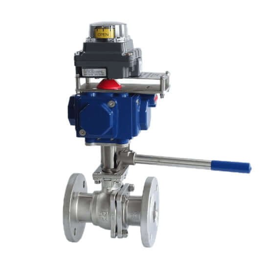
The emgergency shutoff valve normally open, and it specifically engineered to stop the flow of liquid in situations where there is a fire or the temperatures get too high. This type of emergency shut-off valve is typically placed in the fuel line that runs from a storage tank to equipment that burns fuel, include back-up generators which are used when the main power goes out, boilers which provide heating, and various other appliances that burn flammable liquids to operate. By cutting off the liquid flow during emergencies, this valve helps to prevent potentially dangerous situations from worsening.
To meet the needs of the process for continuous operation during a fire incident, it is important to ensure that all safety measures and protocols are in place. This will help in maintaining the ongoing functions without any interruptions even when a fire breaks out.
Chemical plants typically operate in enclosed environments, and in chemical control systems with high fire risks, valves act as the terminal control devices of the regulation system. They are crucial components of the chemical pipeline system, receiving manual or automatic signals to control chemical processes, regulating pressure, preventing backflow, and maintaining stable pressure and leakage. When overpressure occurs, these valves can quickly release excess flammable and explosive media, ensuring the safe operation of pressure vessels and pipeline systems, and preventing fire accidents. When a fire occurs, valves with specific fire-resistant performance can continue to operate normally in high-temperature flames, preventing the leakage of flammable and explosive media and ensuring the safety of production equipment and personnel. Therefore, implementing corresponding fire safety measures for valves is of great significance. Different valves have different specifications and fire testing methods, but specific fire safety measures can be formulated by analyzing the valve structure and causes of fire safety failures.
Under normal operating pressure, if the sealing surface between the valve core and the valve body leaks beyond allowable limits, it can lead to continuous loss of media. Commonly, the sealing surfaces of control valves are metal-to-metal, and continuous leakage can damage the hard sealing materials. Achieving zero leakage under pressurized conditions is very challenging. Therefore, during a fire, regardless of the valve’s sealing structure, spring force, or external pressure changes, the primary consideration should be ensuring metal-to-metal contact between the valve core and valve body to minimize internal leakage. This prevents flammable media from entering the fire. Methods to reduce internal leakage during a fire include regular valve maintenance, ensuring the quality of the sealing surface, improving sealing material quality to reduce damage, and proper valve selection to avoid erosion and cavitation.
External leakage of valves typically falls into three scenarios:
a) Insufficient or Uneven Bolt Tightening on Joint Surfaces: This causes poor sealing. The solution is to adjust the bolt tightness using a diagonal tightening method while measuring the gaps until the desired torque is reached, ensuring consistent gaps.
b) Non-Standard Serrated Gaskets on Joint Surfaces: Radial scratches, poor parallelism, overly sharp or steep serrations can lead to sealing failure and leakage. Ensuring the quality of spare parts by using standard serrated gaskets can prevent this issue.
c) Poor Flatness or Hard Debris on Joint Surfaces: This can cause sealing failure. The valve should be disassembled, and the joint surfaces should be re-ground to meet quality standards. Clean the surfaces during assembly to prevent debris from entering.
To minimize external leakage during a fire, fire-resistant stem sealing materials should be used, avoid large gasket-style body connections, and improve the fire resistance of various materials.
To prevent fire hazards from escalating into large-scale fires or chain explosions and to create favorable conditions for other firefighting measures, it is crucial to ensure that valves can operate normally and continuously after burning. Achieving this requires that not only the valve body components meet fire safety requirements, but also the actuators and their piping and wiring adopt fire-safe designs.
Actuators use liquid, gas, electricity, or other energy sources converted by motors, cylinders, or other devices to drive operations. Common types include pneumatic and electric actuators. Pneumatic actuators receive air pressure signals from controllers or positioners, converting them into linear displacement to drive the valve, mainly diaphragm or piston types. Electric actuators use electrical power as the driving energy, typically using three-phase power for large valves and single-phase power for smaller valves.
In industrial applications, valves typically use spring-type pneumatic diaphragm actuators. During a fire, the low melting point diaphragm quickly fails, causing the spring to move the valve to a safe position. Piston-type reciprocating spring actuators have fusible plugs that melt at specific temperatures, releasing cylinder pressure and allowing the spring or compressed air to move the valve to a safe position. Some valves use electric actuators with spring return functions, which, upon reaching the melting point of fusible components during a fire, activate the actuator’s trigger to drive the valve to a safe position.
To ensure actuators function normally after catching fire, three protective methods can be used: fireproof coatings, sprinklers, or insulation materials.
Fireproof Coatings on Actuators: Applying fireproof coatings can ensure actuators operate normally during a fire. Tests have shown that actuators can function for 42 minutes in flames reaching 760–927°C with such coatings, with springs and seals remaining unaffected. Care must be taken not to cover sealing parts during application, and actuators with aluminum shells are not recommended due to their low melting points.
Sprinkler Systems on Actuators: Automatic sprinklers can extinguish fires and cool down the actuators, but they pose significant risks as water supply systems are often damaged during fires. They also require substantial installation space and maintenance costs, increasing investment.
Fireproof Hoods Made of Insulating Materials: Fireproof hoods control temperature changes within, ensuring actuators’ temperature rise does not exceed 30–40°C within 30 minutes (normal ambient temperature around 40°C, actuator failure temperature 70–80°C). These hoods are flexible, easy to maintain, and ideal for chemical plant valves. They can be customized based on valve shapes and made from high thermal insulation materials like mineral wool, wrapped in a special metal frame for effective isolation. However, they occupy significant space, require custom designs, and need professional removal and inspection during maintenance outages.
The American Petroleum Institute (API) has established fire tests for valves used in the oil and gas industry, such as ISO 10497, API 607, API 6FA, BS 5146, and BS 6755. These tests consider the causes and spread of fires, the type of fluids used, the peak temperatures during a fire, the valve’s sealing integrity, and the valve’s capabilities after the fire.
Scope: This standard applies to quarter-turn valves and non-metallic seated valves, such as ball valves, butterfly valves, and plug valves. The following valve devices are not covered by this standard: fire test requirements for drive devices (e.g., electric, pneumatic, hydraulic) other than manual gearboxes or similar mechanisms, which are typically part of the valve assembly. API 607 is for soft-seated (non-metallic) valves and cannot be used for metal-seated valves.
Detailed Process for API 607 Fire Certification:
Scope: This standard applies to API 6A and API 6D valves, such as ball valves, gate valves, and plug valves. The API 6FA fire test specification is a universal standard that can be used for both soft-seated and metal-seated valves; check valves are not covered by this standard.
Scope: This standard specifically applies to check valves.
Scope: ISO 10497 is a fire test standard for manually operated valves. It excludes the fire test requirements for drive devices (e.g., electric, pneumatic, hydraulic) other than manual gearboxes or similar mechanisms that are part of the valve assembly. ISO 10497 certification provides a global standard for valve fire testing, ensuring valves can maintain a tight shutoff when exposed to fire.
Often, in various materials, valves are said to have fire-resistant functions. This is not entirely accurate. For example, API 607’s standard title is “Fire Test for Soft Seated Quarter-Turn Valves”; API 6FA is titled “Specification for Fire Test for Valves.” Therefore, the correct term should be that the valve has fire-resistant properties. This document does not strictly differentiate between these terms.
Standards and Definitions:
Definition:
Fire Test Diameter and Pressure Rating Evaluation:
API 607 is a critical standard established by the American Petroleum Institute (API) for fire testing quarter-turn valves with non-metallic seating. This standard ensures that such valves can maintain their integrity and functionality during and after a fire, preventing leakage of flammable or hazardous materials.
API 607 specifically applies to quarter-turn valves and other types of valves that utilize non-metallic seating, including:
The standard does not cover actuators or other valve accessories unless they are integral to the valve’s operation.
To pass the API 607 fire test, valves must meet the following acceptance criteria:
Valves that pass the API 607 fire test demonstrate:
The fire test for valves under API 607 includes the following key requirements and procedures:
Pre-Test Inspection:
Test Setup:
Fire Exposure:
Leakage Measurement:
Post-Fire Testing:
Operational Testing:
Documentation and Reporting:
According to widely accepted firefighting strategies, if a fire cannot be extinguished within 30 minutes, evacuation and containment strategies are implemented. Fire tests last for 30 minutes to ensure that fire-safe valves can operate after exposure to high temperatures. During the test, the valve is filled with water and operated at temperatures between 750-1000°C (1382-1832°F) for 30 minutes, while monitoring the external and internal leakage of the sealing areas and seats. If the leakage exceeds acceptable limits, the valve may not be suitable for fire-safe applications.
When selecting fire-safe valves, the terms “fire safe design” and “fire testing” sound similar but have different meanings.
Fire protection features are considered in the design but are not specifically tested for fire performance.
Valves are tested by manufacturers or testing facilities but lack approval from third-party authoritative organizations.
Comprehensive testing, approval, and certification by an authorized third-party organization.
Fire-safe valves are installed in pipelines or equipment in flammable and explosive environments. When a fire occurs, they can continue to operate normally or isolate materials in an emergency. Both pneumatic and electric valves use fire safety measures such as fireproof hoods. Additionally, fire-resistant cables and fireproof wrapping for gas supply lines and cable trays are needed to achieve overall fire safety.
Key design details for valve sealing include:
Understanding valve sealing performance helps identify leakage points and propose different anti-leakage measures, which significantly guide the overall fire-safe design of valves.
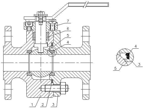
In the closed position, when the seal ring is burned away, the ball remains in position. For floating ball valves with fireproof requirements, three key aspects need attention:
Through these three points, floating ball valves can effectively achieve their fireproof performance in a fire.
Key components include the valve body, gasket, valve bonnet, sealing ring, ball, packing, and packing gland. When the sealing ring is burned away, the ball can rely on the fireproof boss for a certain sealing performance. Key considerations:

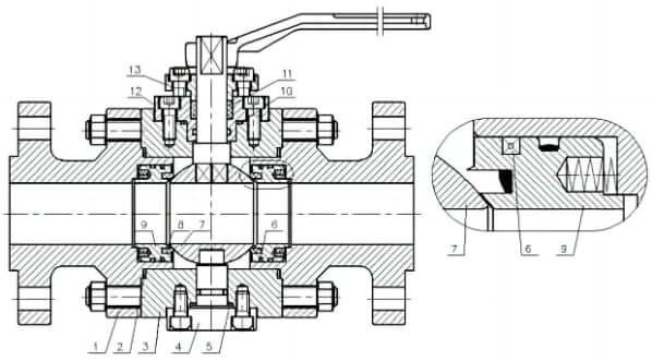
In the closed position, when the seal ring is burned away, the ball remains in position. For trunnion ball valves with fireproof requirements, three key aspects need attention:
Through these three points, trunnion ball valves can effectively achieve their fireproof performance in a fire.
Key components include the valve cover, gasket, valve body, back cover, asbestos rope, ball, sealing ring, support ring, packing, packing gland, and trunnion. Key considerations:

Actuated valves consist of two main components: the actuator and the valve body. The fire protection design requirements for these components are specified in SH/T 3005—2016. According to this standard, if the process requires the actuated valve to have fire protection, a fire-safe control valve meeting API 607 or API 6FA standards should be selected. Additionally, the fire protection requirements for shutoff valves should comply with the relevant provisions and process requirements of GB 50160—2008. For example, “The extraction pipeline of LPG equipment should be equipped with a shutoff valve near the base of the equipment. If the volume of the LPG equipment exceeds 50 m³ and the fire distance between the equipment and its extraction pump is less than 15 meters, the shutoff valve should be a remotely controlled valve with manual functionality. The local operation button of the remote control valve should not be less than 15 meters from the extraction pump.” There are no specific fire test requirements for electric, pneumatic, or hydraulic actuators in the related standard testing procedures.
Exclusions and Additional Standards:
In most industrial applications, valves are not exposed to fires or other extreme temperatures. Under normal operations, the interface between the valve body and closure components should be capable of sealing shut. Users demand that valves exhibit both excellent sealing performance and fire resistance during normal operations. Many manufacturers address this complex requirement by developing various “soft” and “hard” sealing assemblies. Both types of assemblies should maintain metal-to-metal contact sealing after being exposed to fire. Hard seals are typically made of metal or hard alloys, which are inherently fire-resistant. Soft seals are made from PTFE, PEEK, or other elastic materials with melting points below 370°C. While soft seals may degrade in a fire, the system’s pressure, valve plate rotation force, spring force, or gravity should maintain metal-to-metal contact. However, the post-fire safety of many soft-seated valves is not ideal, necessitating stricter standards for testing, analyzing, and comparing the fire performance of valves.
SH/T 3005—2016 specifies that “switching valves should use metal-seated valve seats and internal components, fire-resistant gaskets, and enhanced flexible graphite packing. Metal sealing requirements can also be achieved through specially designed soft-seated valve seats, ensuring that when the soft seat melts during a fire, the valve ultimately achieves metal-to-metal sealing.”
Fire resistance in valves is defined as the ability to maintain normal operation in high-temperature flames. Fire testing is the only method to determine a valve’s fire resistance. Different manufacturers’ valves may only meet one or two fire standards. Fire performance testing not only includes API and ISO regulations but also other national and organizational standards, such as European BS standards, which should be distinguished in practical engineering applications.
Made of strong materials and seals, these valves are designed to withstand high temperatures without damage.
Typically achieved through springs or compressed air in pneumatic actuators. Electric actuators may include backup batteries or mechanical spring mechanisms.
Calculate the actuator’s operating temperature based on the maximum environmental temperature and the highest temperature of the medium flowing through the valve.
Ensure that electric actuators have a failure temperature of 70°C and pneumatic actuators have a failure temperature of 80°C.
Combine the detailed dimensions and layout conditions of the valve and actuator to finalize the fire shield design.
The fire shield consists of multiple layers: fiberglass, stainless steel mesh, high-density ceramic wool, and fiberglass.
Certification:
Emergency Shutoff Valves: According to API RP 553, emergency shutoff valves are designed to prevent uncontrolled release of flammable or toxic substances. If an emergency shutoff valve is located within a fire zone (a minimum radius of 7.6 meters from the leak source), it should be a fire-safe valve. API RP 553 defines four categories of emergency shutoff valves and their respective installation positions.
Please fill out the form below, and we will be in touch within 24 hours.
For urgent inquiry, please feel free to call or add Wechat/Whatsapp via +86 199 2125 0077.